Table of Contents
VCS Shock Testing
Create New Test
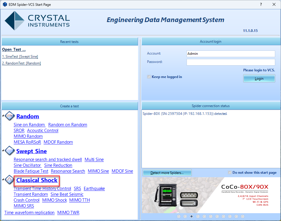
To create a new test, first open up EDM. On the VCS Start Page, select Classical Shock under the Create a test tab.
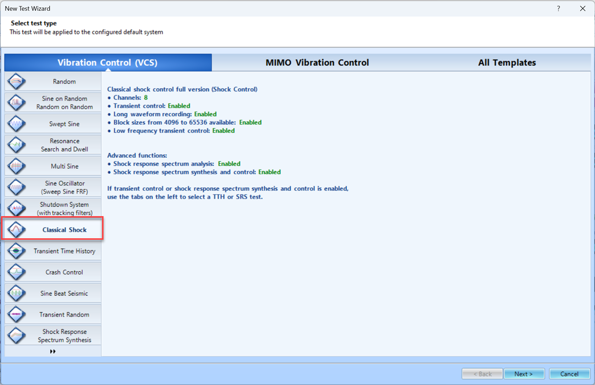
The New Test Wizard will now open up. From here, select Classical Shock again and then press Next.
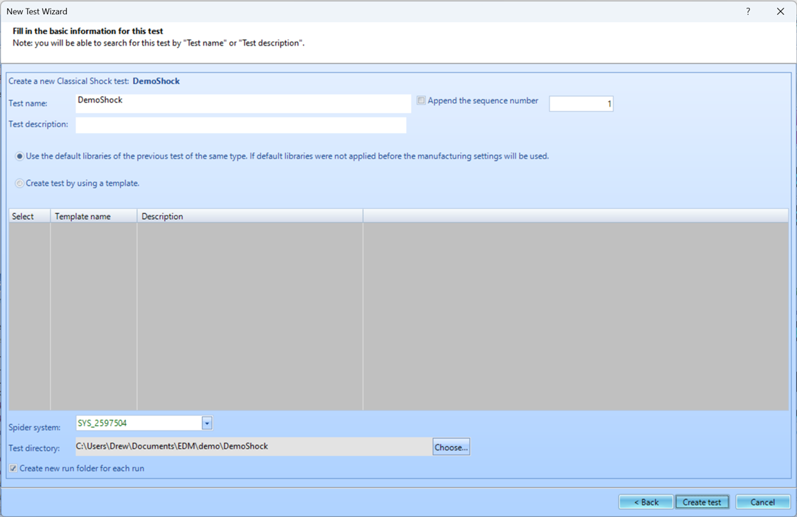
Finally, give the test a name and select the Spider system that will be used to run the test. Once all is complete, press Create.
Test Configuration
The test will now need to be configured to run. This includes inputting information regarding the shaker, creating the schedule for the test to follow, and determining the parameters for the frequency analysis. To access the Test Configuration menu, press the Config button that can be found on the right side of the screen.
 Shaker Parameters
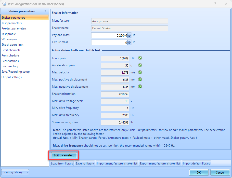
Click on Edit Parameters and enter the information from the shaker specifications. This is important for the safety of the shaker and testing unit.
Test Parameters
The Test parameters section in the Test Configuration window has settings The analysis parameters, pulse interval, output drive voltage limit, and abort sensitivity settings.
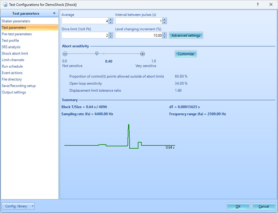
Interval Between Pulses: The time period between successive pulses. The value should be large enough for the system’s response to dampen out after a pulse. It is effective when it is larger than block time.
Test Profile
The Test Profile page is where the pulse shape and time characteristics are set. The window is divided into three sections: the top shows a plot of the pulse shape in acceleration, velocity, and displacement units. The bottom left has settings for the pulse parameters, and the right has settings for the compensation parameters and comparison to shaker parameters.
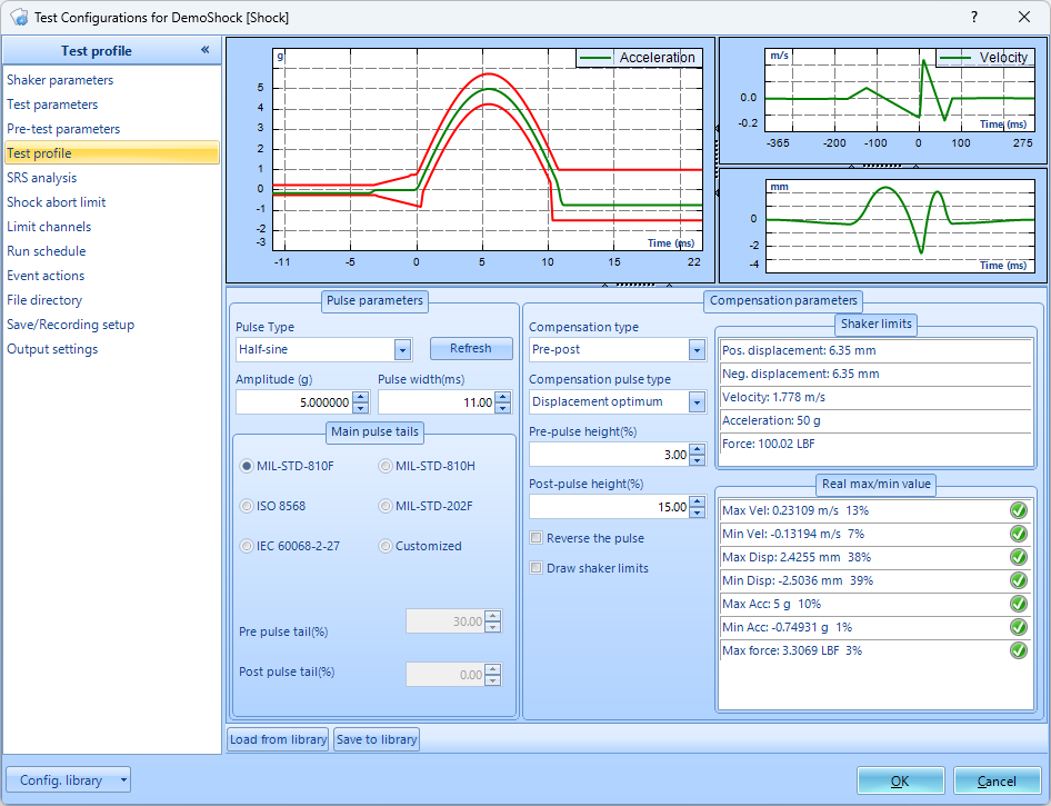
Pulse Type: Pulse Type is the shape of the main pulse. The options are half-sine, terminal-peak sawtooth, initial-peak sawtooth, triangle, rectangle, trapezoid, and haver-sine. The shapes have different frequency characteristics and are suitable for simulated different impulse conditions. Many testing standards specify the pulse shape to be used.
 Amplitude/Width: Amplitude sets the peak acceleration value of the pulse. Pulse width sets the width of the pulse in milliseconds. Narrower pulses have greater high-frequency components.
Pulse Tails: Main pulse tails are the compensation tails described below. The time length of the pre- and post-tails can be set according to five standards: MIL-STD-810, MIL-STD-202F, MIL-STD-810H, the ISO 8568 mechanical shock test standard, and the IEC 60068-2-27 mechanical shock test standard. They can also be set to custom lengths as a percentage of the main pulse width.
Min/Max Values: Real Max/Min Value table, the characteristics of the pulse are shown and compared with the shaker limits. Each row has an icon that is either green if the associated pulse characteristic is less than 50% of the shaker limit, yellow if is great than 50%, and red if it is 100% or over the limit. Before starting a shock test, all these icons should be green or yellow.
Run Schedule
When a test is run, it executes the entries in the run schedule. These entries define test stages at certain levels and durations.
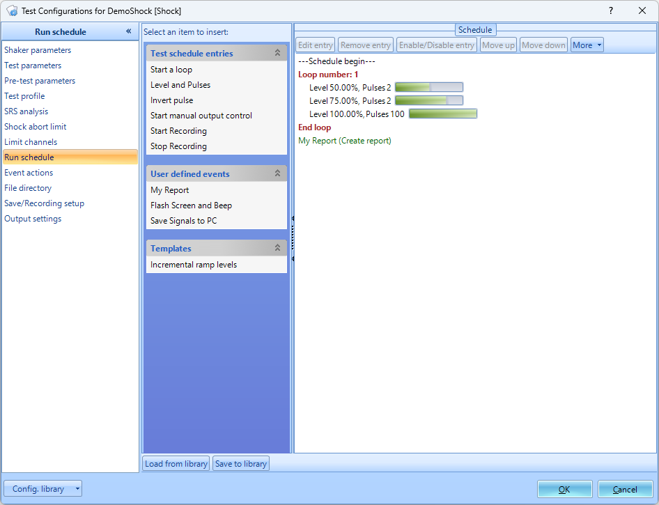
Level and Pulses: Level and Pulses output the set number of pulses at the set level, given in percent.
Inverse Pulse: Inverse Pulse will make all subsequent pulses inverted.
Input Channels
The input channels will now need to be set up. All sensors will to be properly configured before testing. The Input Channels menu can be found through Setup → Input Channels.
 Channel Type
Control vs. Monitor. When running a test, there will need to be at least one control sensor. The control sensor is used to monitor the actual vibration levels that the shaker is producing. It then sends this data to the controller so that it maintains the targeted profile. This sensor should be mounted somewhere on the shaker/slip table itself, not the Device Under Test (DUT). Monitor sensors will show the levels that the DUT itself is experiencing.
 Measurement Quantity
Defines the physical unit that will be measured by the sensor connected to the channel.
Sensitivity
Sets the proportionality factor for the measurement (millivolts per engineering unit) given as a parameter of the sensor.\\Input Mode
There are five modes in which the inputs can operate:
DC-Differential- In the DC-Differential mode, neither of the input connections is referenced to the local ground. The input is taken as the potential difference between the two input terminals, and any potential in common with both terminals is canceled out. The Common Mode Voltage (CMV) will be rejected as long as the overall input voltage level does not saturate the input gain stage. Beware that very high CMV will cause clipping and may damage the input circuitry. Signals with a nonzero mean (DC component) can be measured in this mode.
DC-Single End- In single-ended mode, one of the input terminals is grounded and the input is taken as the potential difference of the center terminal with respect to this ground. Use this mode when the input needs to be grounded to reduce EMI noise or static buildup. Do not use this mode when the signal source is ground referenced or ground loop interference may result. This mode also allows signals with a non-zero mean to be measured.
AC-Differential- AC-Differential is a differential input mode that applies a low-frequency high-pass (DC-blocking) analog filter to the input. It rejects common mode signals and DC components in the input signal. Use this when DC and low-frequency AC voltage measurements are not required or when a DC bias voltage is present. The analog high-pass filter has a cutoff frequency of -3dB at 0.3 Hz, and -0.1dB at 0.7 Hz for the IEPE input mode.
AC-Single End- AC-Single End grounds one of the input terminals and enables the DC-blocking analog filter. Use this mode for non-ground referenced sources where measuring the DC or low-frequency components are not required. It shares the same high-pass filter as that of AC-Differential.
IEPE (ICP)- All Crystal Instruments products support IEPE (Integral Electronic PiezoElectric) constant current output type input channels. IEPE refers to a class of transducers that are packaged with built-in voltage amplifiers powered by a constant current. These circuits are powered by a 4 mA constant current source at roughly 21 Volts.
Charge- Some sensors provide a high-impedance charge output. Usually, these are high-sensitivity piezoelectric units that lack a built-in voltage mode amplifier (i.e. IEPE), allowing them to be used in high-temperature environments. The Spider-81 front-end module has a built-in charge amplifier that allows the system to read the output of these sensors
Running the Test
Now that all of the parameters for the test have been setup, the test is ready to run. Here are the final steps to start the test.
- Press the Connect button to connect to the controller.
- Press the Run button.
- The Spider Check List will now appear. Here you can check the settings of the test and verify that all is set up properly. Press Start once this has been verified.
- The Pre-Test will now begin. This will verify that the control loop is properly established and provide data that the control loop needs.
- The test is now running